Operating Multi-Tenant Dataspace Environments

Operating multi-tenant dataspace environments requires an architectural model that is both scalable and predictable. The Virtual Connector(EDC-V), combined with the Connector Fabric Manager(CFM), provides exactly that: a way to deliver dataspace capabilities as a managed platform rather than a collection of individual connector deployments. Instead of treating each participant as a separate infrastructure footprint, service virtualization turns participant contexts into lightweight, repeatable units that the platform can provision and operate at scale.
In practice, this is how cloud providers and enterprises build digital ecosystems at scale: by making partner participation repeatable, governed, and interoperable with a cost-effective multi-tenant infrastructure.
This guide explains how to run that enterprise platform effectively. It brings the core pieces of the Eclipse Dataspace Components ecosystem: connector data and controlplane, catalog, identity, access and usage policies, contract negotiation into a coherent operational model that cloud providers and data platform teams can adopt with confidence. Whether you're onboarding a participant, a virtual participant agent (VPA), or scaling runtime capacity, the goal is to give you a blueprint for reliable operations across multiple dataspaces.
The guide is structured around three perspectives that together form the foundation for operating EDC-V in production:
- Operation: the cloud-native foundation, the CFM management plane, and the shared runtime cells that host VPA contexts.
- Participant experience: onboarding, credential handling, catalog publication, and sharing workflows easily manageable through the customer portal.
- Data Sharing: the protocol choreography for sharing, trust evaluation, and separation of control plane and data plane responsibilities that enable trusted data sharing.
This guide is written for teams responsible for running a dataspace as a service for multiple customers, those who need to understand how to operate these components cost-effectively and scaleably. The aim is to provide a practical, implementation-oriented view of multi-tenant operation: one that turns dataspaces into a production-ready environment.
Summary
At a high level, operating EDC-V at scale means running a management plane (CFM) plus a shared runtime that hosts isolated VPA contexts. The goal is to keep that runtime predictable to operate and straightforward to scale.
- As Operator you run: a management plane (CFM) plus shared runtime cells hosting Virtual Participant Agents (VPAs).
- Your customers use: the Customer Portal to onboard, manage Decentralized Identifiers (DIDs) and credentials, publish and contract data, and configure data planes.
- Data moves: peer-to-peer between participants over open protocols: Decentralized Claims Protocol (DCP), Dataspace Protocol (DSP), Data Plane Signaling Protocol (DPS).
Operationally, onboarding and lifecycle management are centralized, while trust and sharing decisions remain decentralized between participants.
Benefits
This operating model is worth implementing when you’re trying to make EDC-based data sharing repeatable and operable. The goal is to turn “deploy a connector project” into “provision a participant context.”
- Operations cost: operate shared cells and automate provisioning instead of running per-tenant stacks.
- Onboarding: move onboarding from hand-crafted deployments to CFM workflows and templates.
- Scalability: add capacity by scaling cells, not by multiplying bespoke deployments.
- Sovereignty: policy decisions stay peer-to-peer; data planes run close to the data.
- Interoperability:
DCP/DSP/DPSprotocols keep you compatible with external and self-hosted participants.
If you need the strategic framing and business outcomes, read the Decision Maker Guide. This guide stays focused on what you have to build and operate.
How to Read This Guide
This guide answers three questions:
- What you run (platform architecture)
- What your customers do (tenant experience)
- How data actually moves (sharing runtime)
Use this as a map. Each part introduces a boundary (operational, product, network) that the later parts assume, so if something feels unclear, it’s usually because a boundary hasn’t been made explicit yet.
Who This Guide Is For:
This guide is written for teams responsible for operating, securing enterprise data sharing platforms:
- Enterprise architects who need to define the generic runtime model and trust boundaries
- Solutions architects mapping customer constraints to deployment patterns
- Platform teams deploying and operating dataspace components at scale
If you’re building business apps or value added services, you’ll still benefit from the “how data moves” section, but this guide stays focused on the platform and operational model rather than app-level connector configuration.
Part 1: Platform Architecture for Operators
This section starts from the operator’s perspective: the components you deploy, monitor, and scale. It intentionally defers end-user workflows and sharing choreography until the platform model and operational boundaries are clearly established.
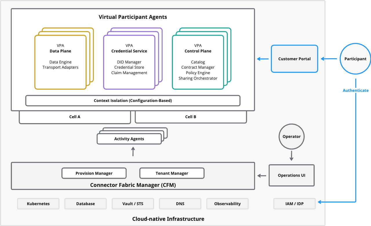
The platform is intentionally layered so you can reason about responsibility and failure modes. Think in three planes: a cloud-native foundation, a management plane that provisions participant contexts, and a runtime plane where the dataspace protocols execute.
In the operations view, runtime isolation is configuration-based: VPA metadata defines the context, and cells provide the underlying capacity. This is what enables the same shared services to host many participants while keeping contexts separated.
| Layer | What it is | What it’s responsible for |
|---|---|---|
| Cloud-native infrastructure | Kubernetes, storage, secrets, DNS, IAM, observability | Reliability primitives, persistence, identity, operational tooling |
Connector Fabric Manager (CFM) | Management plane | Provisioning workflows, tenant metadata, and VPA lifecycle automation |
Virtual Participant Agents (VPAs) | Runtime plane | Protocol endpoints, policy decisions, data flow execution |
Roles in an EDC-V deployment are logical roles. Some map to human-facing UIs, while others are machine identities used for automation and tightly controlled high-privilege access.
To make responsibilities and security boundaries explicit, EDC-V separates participant self-service from platform administration and provisioning automation.
| Role | Typical client | Responsibilities |
|---|---|---|
| Participant | Customer Portal (via a UI backend) | Manage participant-scoped resources such as catalogs/assets, policies, contracts, and data flow |
| Provisioner | CFM / provisioning automation | Onboard and manage participant contexts (create/configure tenants); must not manipulate participant-owned business data |
| Operator | Operations UI + platform tooling (e.g., Kubernetes/IAM) | Deploy and operate the platform infrastructure; monitor, scale, and troubleshoot cells and shared services |
| Admin (emergency) | Restricted automation / privileged operator access | Full access for initial setup and emergency recovery; not intended for day-to-day use |
The Infrastructure Foundation
Run EDC-V on standard cloud-native infrastructure and keep the foundation intentionally “simple”. Your goal at this layer is operational certainty: predictable failure modes, repeatable deployment patterns, and runbooks your teams already know how to execute.
Treat identity, secrets, persistence, networking, and observability as first-class dependencies. They sit on the critical path for onboarding and day-to-day operation, and they define how confidently you can scale cells, rotate credentials, recover from incidents, and demonstrate compliance. Prefer managed offerings and proven platform primitives over custom infrastructure—especially for IAM/IDP integration, secret storage, database backups, and telemetry pipelines.
| Component | Purpose |
|---|---|
Kubernetes | Container orchestration and scaling |
PostgreSQL | State persistence across components |
Vault / STS | Secrets, key material, and token-related infrastructure |
DNS | Request routing and DID resolution |
Observability | Metrics, logging, and tracing |
IAM/IDP | Authentication for admins and participants |
Keep the platform “cloud-native by default.” If you need bespoke infra to run EDC-V, you’re adding cost without improving trust.
Put complexity where it pays: trust, policy, and interoperability. Where possible, rely on well-understood primitives for orchestration, persistence, and IAM.
In Kubernetes-based environments, a Kubernetes Operator can be a practical way to standardize how you deploy and wire the core runtime components inside a cell (for example Control Plane, Data Plane, and Credential Service). It won’t replace CFM—but it can reduce drift and make cell bring-up and baseline configuration repeatable across clusters.
The Connector Fabric Manager
The Connector Fabric Manager (CFM) is your management plane. It provisions participant contexts and automates the lifecycle of VPAs. You can think of it as an orchestration layer for service virtualization: it creates runtime, but it is not the runtime.
For the full architectural model (and the key “where do I extend this as a cloud provider?” details), see the CFM system architecture documentation.
At a minimum, CFM is designed to run as a reliable message-based system backed by a PostgreSQL database and a messaging middleware (by default, NATS JetStream). That bias toward asynchronous coordination is what lets provisioning workflows span multiple steps without tight coupling between subsystems.
The CFM comprises three subsystems:
| Subsystem | Role |
|---|---|
| Tenant Manager (TM) | Persists tenancy and virtualization metadata; exposes a REST API; initiates deployments |
| Provision Manager (PM) | Executes stateful orchestrations (workflows) for onboarding and VPA lifecycle |
| Activity Agents | Asynchronously process orchestration steps in isolated security contexts |
In an EDC-V environment, treat the Tenant Manager as the metadata control point and the Provision Manager as the execution engine. The Tenant Manager modifies virtualization entities (e.g., tenant, participant profile, VPA targeting) and sends message-based requests to the Provision Manager, which runs an orchestration until completion and reports status back asynchronously.
The CFM runtime is also designed to be modular: it can be composed from discrete modules (“service assemblies”) with explicit dependencies and lifecycle stages. This keeps the default architecture small while allowing you to adapt the runtime to different environments and operational requirements.
Activity Agents are where you integrate with your cloud platform and enforce consistency across tenants. They also isolate infrastructure secrets and access from the Provision Manager, creating bounded security contexts even within a single provisioning workflow.
Typical Activity Agent responsibilities include:
- Deploy to Kubernetes
- Configure Vault namespaces
- Set up DNS entries
This separation keeps provisioning reliable under change: you can roll upgrades, restart workers, or throttle onboarding without rewriting the control flow logic that defines “what a participant context is.”
Communication happens through NATS JetStream, providing reliable, decoupled messaging between components. JetStream persistence and durable consumption is what makes long-running orchestrations resilient to restarts and transient failures.
The CFM provisions participant contexts and runtime configuration, but it is not in the trust-decision path. The CFM can be completely unavailable—undergoing maintenance, experiencing an outage, being upgraded—and live data sharing continues uninterrupted. Trust decisions are made locally, per interaction, between participant VPAs with no dependency on CFM.
Operationally, this split lets you plan downtime, upgrades, and incident response without turning every change into a full outage of the dataspace environment.
- Maintenance windows are possible without stopping the data flow
- Outages block onboarding and provisioning, not runtime sharing
- Separate SLOs for management plane vs runtime
The practical consequence is that you can run “platform SRE” playbooks for CFM without touching the runtime trust decisions and sharing execution. That’s exactly the separation you want when onboarding is degraded but existing participants are actively negotiating and transferring.
Virtual Participant Agents
Virtual Participant Agents (VPAs) are the unit of runtime isolation and administrative control in a service-virtualized EDC-V deployment. A VPA represents the runtime context for a participant profile, but it is not a dedicated per-tenant stack: shared services create an isolation context on demand from VPA metadata (a configuration-based isolation model).
Each VPA is targeted to a cell (a homogeneous deployment zone such as a Kubernetes cluster). Because the context is defined by metadata rather than per-tenant processes, CFM can rebalance capacity or migrate contexts by re-targeting the VPA and updating routing, without rebuilding the participant from scratch.
EDC-V provisions three VPA types—Control Plane, Credential Service, and Data Plane—each with a distinct responsibility and trust role. In production, expect multiple instances of each type for capacity and separation; participants commonly use more than one Data Plane (for example, separate transport adapters for HTTP, S3, or OPC-UA).
- Control Plane VPA
- Credential Service VPA
- Data Plane VPA
A Control Plane VPA is where trust and policy decisions are evaluated. It publishes catalogs, negotiates contracts, and produces the contract agreements that authorize access.
When a consumer requests access, the control plane requests proofs, evaluates policies, and either establishes an agreement or rejects the request. Only after authorization does it coordinate the resulting data flow by signaling data planes to execute it.
For a deeper overview (catalogs, contract negotiation, and policy monitoring), see the EDC Control Plane documentation.
A Credential Service VPA stores verifiable credentials and produces the cryptographic material needed to prove identity and claims. It’s where DID lifecycle (DID Manager) and proof/presentation composition (Claim Management) live.
Identity Hub note: In the Eclipse ecosystem, the canonical implementation that provides wallet/credential capabilities is Identity Hub. See the EDC Identity Hub documentation. In this guide we use the runtime role name Credential Service (because that’s how operators and API surfaces usually frame it), but the underlying implementation and concepts align.
If you need the underlying standards vocabulary: W3C DID Core, DID:web method, and W3C Verifiable Credentials Data Model.
This keeps identity concerns out of your business apps and out of the data engine.
A Data Plane VPA is the data execution layer for sharing. It executes data flows once a decision has been made, and it is optimized for throughput and proximity to data sources.
Treat it as the trusted execution layer for sharing: it enforces the secure data path, but policy and authorization decisions remain in the control plane.
In practice, Data Plane capabilities are often implemented through adapters that encapsulate wire-protocol specifics (for example HTTP, S3, MQTT). This lets a single data plane runtime support multiple adapter technologies, or lets you run multiple data plane instances when you want stricter separation per protocol or environment.
Context Isolation ensures that while VPAs share infrastructure, they are logically isolated. One participant context cannot see or access another participant’s data, credentials, or configuration.
The Mental Model Shift for Multi-Tenant Operations
If you're coming from traditional single-tenant connector deployments, the operational model changes fundamentally. Traditional deployments follow a simple equation: one connector equals one process. You deploy separate infrastructure for each tenant, scale by adding containers, and manage operations on a per-tenant basis.
CFM-managed deployments invert this model. One runtime serves many VPAs. You provision VPA metadata rather than deploying infrastructure. You scale by adding cells—logical groupings of shared resources—rather than individual containers. You manage operations centrally rather than per-tenant.
The table below captures the shift you’re making: from per-tenant deployments to shared runtimes, from “scale containers” to “scale cells,” and from manual operations to configuration-driven provisioning.
| Traditional Deployment | CFM-Managed Deployment |
|---|---|
| One connector = one process | One runtime serves many VPAs |
| Deploy infrastructure per tenant | Provision VPA metadata |
| Scale by adding containers | Scale by adding cells |
| Manage operations per-tenant | Manage operations centrally |
This shift makes scaling sub-linear rather than linear with tenant count. You manage fewer cells with centralized tooling instead of hundreds of per-tenant deployments.
Part 2: Your Customer User Journey
Now that you understand what you're operating, let's look at the platform from the users' perspective. How do organizations onboard? What do they interact with? How do trust frameworks, claims, and policies connect to day-to-day platform workflows?
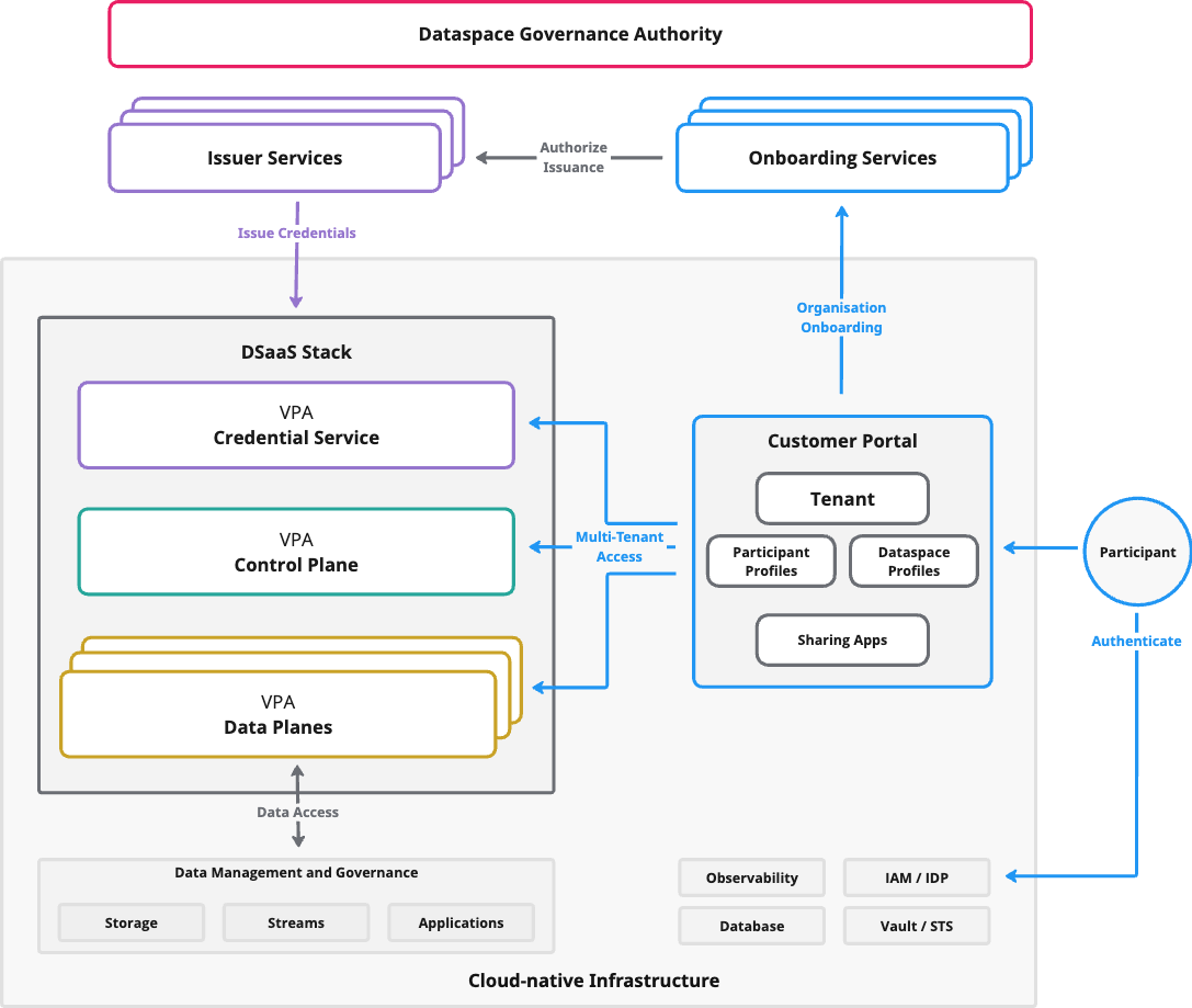
From the tenant’s point of view, your platform is a thin “product surface” on top of a governance-defined trust framework and a protocol-driven runtime. The separation is deliberate: governance defines participation rules and trust requirements, while your EDC-V + CFM deployment makes participation operationally easy.
| Layer | What the tenant experiences | What it means for your product |
|---|---|---|
| Dataspace Governance Authority | Rules, onboarding, issuers, compliance gates | You integrate; you don’t arbitrate membership |
EDC-V runtime | Catalog, negotiation, identity proofs, data flow execution | You provide runtime primitives with service virtualization |
| Customer Portal | Self-service workflows and configuration | The product surface participants use day-to-day |
The Governance Layer
In IDSA/ISO terms, a dataspace is an environment for trusted data sharing anchored in an agreed governance framework: rules, policies, shared semantics, standardized protocols, and the processes and services that make participation operational.
The Dataspace Governance Authority (DSGA) is a functional role that maintains that governance framework and specifies which trust frameworks apply (including membership rules, required attributes/credentials, and minimal shared semantics for interoperability). Importantly, the DSGA is not the runtime-enforcement layer: it defines the model; enforcement is performed by participants at interaction time through identity proofs and policy evaluation.
Understanding this separation is crucial for positioning your platform correctly. Governance defines the framework and joining requirements; your platform operationalizes them by provisioning VPAs and wiring identity and policy flows so participants can engage peer-to-peer using interoperable protocols.
Your platform handles the technical layer; the Governance Authority handles the legal and trust layer.
In practice, dataspace membership is expressed as credentials (e.g., verifiable credentials). The governance framework defines the membership policies and the semantics of the attributes an applicant must present; onboarding processes may include legal and compliance steps before credentials are issued.
To avoid implicit central dependencies (and single points of failure), dataspaces often rely on multiple onboarding and issuer services. These services are not the DSGA itself; they are operated by one or more providers acting on behalf of the DSGA under the governance framework, and participants can choose among the governance-recognized options.
Common services that interact with your platform include:
| Service | Purpose | Operated by |
|---|---|---|
| Onboarding Services | Business verification, legal agreements, compliance checks | Governance-recognized service provider(s) (acting on behalf of the DSGA) |
| Issuer Services (Credential Issuers) | Issue verifiable credentials after approval | Governance-recognized service provider(s) (acting on behalf of the DSGA) |
The interface to your runtime stays the same regardless of who operates these services: issued credentials are stored and presented via the Credential Service VPA.
Authorization and issuance are separate on purpose. Governance defines and enforces the requirements for joining; your platform executes the technical flow.
The Onboarding Journey
With that governance split in mind, the onboarding journey is where it becomes concrete: governance verifies and authorizes membership, while your platform provisions the technical context that receives credentials and enables participation.
The journey has six stages:
- Application to a governance-recognized Onboarding Service (acting on behalf of the DSGA)
- Verification: legal, compliance, and business checks
- Tenant provisioning in your platform (including the credential destination)
- Credential issuance by a governance-recognized Issuer Service, delivered to the tenant’s Credential Service VPA
- Configuration: assets, policies, and applications
- Active participation: catalog discovery, contract negotiation, and data flows
The boundary to internalize is step 2 vs step 3/4: governance verifies and authorizes issuance, and your platform provisions the tenant context that makes credential delivery and subsequent participation operational.
Credential acquisition often involves processes outside your platform entirely—legal agreements, compliance audits, business relationship verification. Your platform facilitates the technical flow, but the business process belongs to the dataspace governance.
The Customer Portal
The Customer Portal is what your customers see and use day-to-day. In this guide, treat it as the product interface for managing a participant’s hosted dataspace footprint on top of EDC-V and CFM administration capabilities.
Practically, the portal is an opinionated view over the service virtualization model: a Tenant (an organization) can have multiple Participant Profiles (each bound to a single identifier such as a DID), participate in one or more dataspaces via Dataspace Profiles, and be served by one or more Virtual Participant Agents (VPAs) targeted to specific runtime cells. Only the UI backend is typically internet-facing; it holds machine credentials and calls administration APIs on behalf of logged-in users.
Two useful reference implementations for this “portal + backend” layer are:
- Cloud-provider UI backend:
Metaform/redline - End-user onboarding GUI (SME onboarding demonstrator):
FraunhoferISST/End-User-API
The portal manages a clear hierarchy of concepts that reflects how organizations actually think about their dataspace participation, and how CFM structures provisioning and isolation:
| Concept | Description |
|---|---|
| Tenant | The organization: customer relationship, billing entity, and support boundary |
| Participant Profiles | Participant identity contexts (e.g., DID-backed); one identifier per profile; multiple profiles are common across business units or identities |
| Dataspace Profiles | Per-dataspace configuration: protocol versioning, trust requirements, and policy/semantics alignment |
| Sharing Apps | Business applications that discover catalogs, negotiate agreements, and initiate/consume data flows via the runtime |
An automotive supplier might have one Dataspace Profile for Catena-X and another for Manufacturing-X, both served by a single infrastructure instance.
Tenant Workflows
After onboarding, most tenant activity is “day-2” configuration and operations through the portal (and the apps it supports):
- Manage participant identity contexts (DIDs, credentials) and join dataspaces by attaching the right trust requirements to the right profile
- Publish offerings (assets) and define access policies
- Negotiate contracts and start data flow via sharing applications
- Configure data-plane connectivity for data paths (endpoints, credentials/secrets, and environment placement)
- Observe and troubleshoot: negotiations, data flow status, and runtime health (within tenant boundaries)
The EDC-V Runtime from the Customer's View
From the customer's perspective, the runtime presents three main touchpoints. The important detail is isolation: the same shared services handle many participants, but each VPA represents a distinct administrative and runtime context.
Under the hood, the Customer Portal and its backend talk to a small set of Administration APIs. These APIs are for machine clients (automation and UI backends), not direct human use.
| Name | Exposed by | Purpose | Content type | Authentication | Intended client |
|---|---|---|---|---|---|
| Management API | Control Plane | Manage assets, policies, and contracts | JSON-LD | OAuth2 | participant, provisioner |
| Identity API | Identity Hub | Manage DIDs, key pairs, and verifiable credentials | JSON | OAuth2 | participant, provisioner |
| Issuer Admin API | Issuer Service | Manage holders, attestations, and credential definitions; manage issuer tenants | JSON-LD | OAuth2 | provisioner |
| Observability API | All components | Readiness and health endpoints | JSON | none | monitoring systems |
| Federated Catalog API | Control Plane (optional) | Query and inspect the federated catalog of data offerings | JSON | OAuth2 | participant |
- Credential Service VPA
- Control Plane VPA
- Data Plane VPA
This is where issued verifiable credentials land and where proofs get assembled for verification. Tenants shouldn’t be thinking about key material and cryptographic formats—only about “do I have the credential, and can I prove it?”
This is where tenants publish offerings, define policies, and negotiate contracts. The value of service virtualization here is a cleaner tenant experience: tenants work with manageable concepts while the platform handles the DSP choreography behind the scenes.
If you need to evolve policy evaluation without redeploying the runtime, EDC-V can support dynamic policy evaluation using CEL (Common Expression Language). For the technical details, see Dynamic policy evaluation in EDC-V with Common Expression Language (CEL).
This is where data actually connects to systems: object stores, APIs, streams, OT gateways, and line-of-business apps. It enables data flow only after authorization is established, which is why it can be optimized and deployed close to the data.
Authentication and Access Control
From a tenant experience standpoint, the key point is that humans typically authenticate to your portal, while the portal backend and automation use machine credentials to call EDC-V Administration APIs on behalf of a tenant’s participant context.
EDC-V Administration APIs are designed for machine clients and use centralized access control with OAuth2. In the API model, EDC-V defines three roles: admin, provisioner, and participant. Operationally, most deployments also distinguish an operator role for infrastructure access, but that role typically sits outside the Administration API authorization model.
| Role | Access | Use case |
|---|---|---|
| Operator | Infrastructure only (Kubernetes, DNS, Vault, IAM) | Initial deployment and ongoing platform operations |
| Admin | Full access to all resources | Emergency access and initial setup |
| Provisioner | Creates participant contexts and manages VPAs | CFM automation and onboarding |
| Participant | Manages own resources | Business apps and day-to-day operations |
Administration APIs use the client_credentials flow. The same token can be used across Control Plane and Credential Service Administration APIs if it carries the correct claims and scopes.
Two claims matter for correctness:
role: one ofadmin,provisioner,participant(and deployment-defined operator access outside Admin APIs)participant_context_id: identifies the participant context the client acts for
Participant-scoped endpoints are typically rooted under "/participants/{participant_context_id}/...", which is how the platform enforces isolation at the API surface.
This boundary is not optional: in EDC-V, identities, roles, scopes, and access privileges are tied to the participant context. Treat participant_context_id as the security unit for both API access and operational troubleshooting.
It is also generally recommended that the OAuth2 client_id is not the same value as the participant_context_id. Treat the participant context as the stable platform identifier, and the client ID as a credential handle that you can rotate and segment.
- Scopes and least privilege: for participant-scoped tokens, keep a
scopeclaim that limits what the client can do (e.g.,management-api:read/management-api:write,identity-api:read/identity-api:write). Avoid wildcard scopes for tenant-facing clients. - Role-separated clients: keep
role=adminfor emergencies only; userole=provisionerfor automation that creates/manages contexts; userole=participantfor tenant day-2 operations. - Token retrieval (typical
client_credentialspattern):
curl -X POST "$TOKEN_URL" \
  -H "Content-Type: application/x-www-form-urlencoded" \
  -d "grant_type=client_credentials&client_id=...&client_secret=..."
Vault Access Boundary (Secrets Isolation)
Most deployments rely on a secrets system (“vault”) for key material and sensitive configuration. Vault access should follow the same isolation boundary as API access: one participant context should only be able to read its own secrets.
A common hardening pattern is to use a dedicated client identity for vault access that is still bound to the same participant_context_id, but is separate from the client identity used for Administration API access. This reduces blast radius (compromising an API client secret does not automatically grant vault access) and supports least privilege if the token requirements differ.
This separation also makes credential rotation and incident response simpler: you can revoke vault access without disrupting tenant application access (and vice versa).
Part 3: Data Sharing Runtime
The first two perspectives showed you the platform and the user experience. Now we examine what makes trusted data sharing actually work: how data flows between organizations while maintaining sovereignty and security.
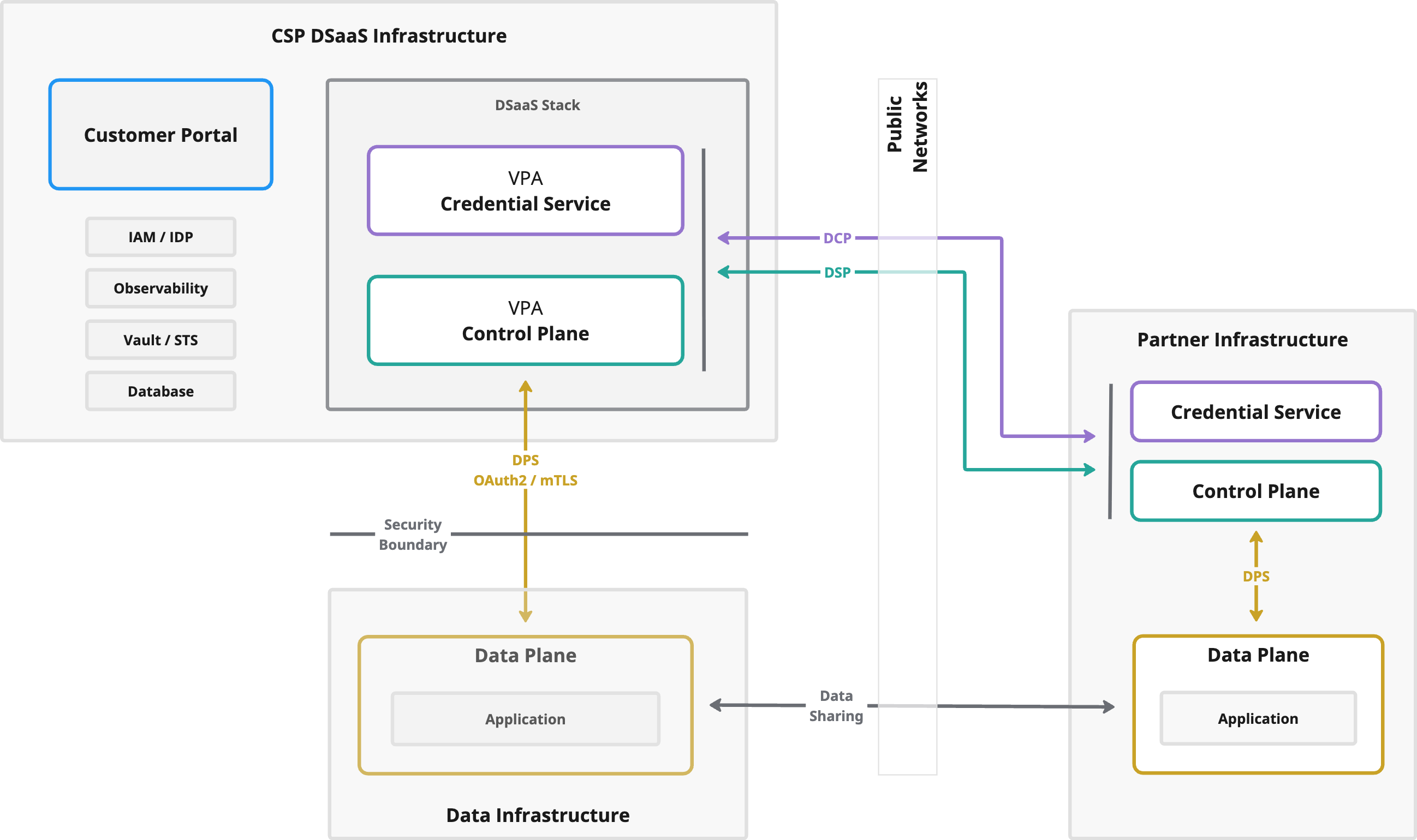
The diagram highlights the most practical reality of production dataspaces: deployment patterns vary. You might run everything as a fully managed service, you might keep execution close to the data (on-prem/edge/regulated regions), or you might interoperate with partners that run their own runtimes. Public networks connect these choices through standardized protocols so partners can integrate without aligning on one topology.
If you find it useful to think in analogies: the Control Plane is the coordination and authorization layer, while the Data Plane is the execution layer. One decides and signals; the other performs the sharing.
Data Plane Deployment Patterns
At runtime, the Control Plane is the coordination and authorization layer, while data planes execute the actual data sharing. This separation is the core reason dataspaces can be both interoperable and sovereign: you can deploy data planes where they fit best—directly beside your control plane for simplicity, or close to the data for latency, connectivity, and residency.
In some products, a Data Plane is also packaged with a dedicated sharing app / UI (for example: upload/download workflows, data flow status, and audit views) that can be embedded into a tenant’s customer portal. Other deployments keep data planes intentionally headless and expose only APIs—both models work as long as the execution layer remains swappable and the partner-facing protocols stay standard.
The data sharing runtime supports three fundamental data plane patterns:
| Type | Direction | Use cases |
|---|---|---|
| Pull | Consumer fetches from provider | API access, on-demand queries, real-time data |
| Push | Provider sends to consumer | Batch exports, event-driven delivery, file transfers |
| Stream | Continuous flow until terminated | IoT sensors, telemetry, real-time monitoring |
In concrete terms, pull often looks like a consumer fetching from an HTTP endpoint or subscribing to a provider queue. Push often looks like a provider uploading to consumer object storage or publishing to a consumer endpoint. Data Plane implementations are where these wire-protocol details live.
For customers with data sovereignty requirements or edge deployments, several patterns address common scenarios:
- Factory/Site Edge Pattern: Data Planes at each site connect to local systems while the Control Plane manages a unified catalog.
- Multi-Protocol Edge Pattern: Separate Data Planes handle OPC-UA, S3, HTTP, and other protocols under one policy model.
- Geographic Distribution Pattern: Data Planes deploy in required regions to keep data flow within jurisdiction.
In real deployments, it’s normal to run multiple data planes: per site, per protocol, per region, or per tenant—while keeping the trust-decision model consistent in the Control Plane.
When policy requirements change frequently across dataspaces, dynamic policy evaluation can reduce operational coupling between policy updates and runtime deployments. For one approach used in EDC-V, see Dynamic policy evaluation in EDC-V with Common Expression Language (CEL).
Protocols for Trusted Data Sharing
At the technical layer of a dataspace (separate from the economic and legislative layers), participants are represented by software services (“connectors”) that need to talk to each other reliably—even when they come from different vendors or are deployed in very different environments. In standardization terms, this is what makes dataspaces “connecting agents” across communities.
When a partner wants to access data from one of your customers, the protocols execute in sequence:
DCPidentity verification between Credential ServicesDSPcatalog discovery and contract negotiationDPSsignaling from Control Plane to Data Plane- Data sharing execution between data planes
Interoperability is achieved by standardizing three distinct problem spaces:
| Protocol | Connects | Why it exists (what it is used for) |
|---|---|---|
DCP | Credential Service ↔ Credential Service | Establish who you are in a decentralized way: exchange and verify identity material and claims (e.g., verifiable credentials) so DSP policy checks can be evaluated against participant attributes (spec). |
DSP | Control Plane ↔ Control Plane | Establish what is being shared and under which rules: discover catalogs and contract offers, negotiate a contract agreement, and coordinate the agreement-backed sharing process between participants (spec). |
DPS | Control Plane ↔ Data Plane | Establish how the agreed sharing is executed at runtime: signal START/SUSPEND/TERMINATE over a shared data flow state machine (push or pull) so data planes can be swapped or scaled independently of the control plane (docs). |
A practical way to remember the split: DCP proves the parties, DSP proves the agreement, and DPS drives the execution. After that, the actual bytes move over wire protocols (HTTP, S3, MQTT, industrial protocols, …) between data planes, based on what was negotiated.
Interoperability: validate with TCKs
To make sure different connector implementations actually interoperate, use the conformance suites: DCP TCK (Credential Service) and DSP TCK (Control Plane). This is your fastest baseline before you debug partner-specific configuration.
The Data Plane Ecosystem
In a hosted dataspace, the Data Plane is the execution layer that bridges modern data ecosystems across boundaries: APIs, object storage, event/streaming platforms, and OT/edge gateways. It moves bytes over real transports while enforcing runtime access constraints derived from the negotiated agreement (identity, policy, and contract).
State-of-the-art deployments treat data planes as capability-addressable execution services: you run multiple specialized data planes and let the control plane select the right one per transfer based on capabilities, placement, and health.
- Hybrid, multi-protocol connectivity:
HTTP/API access,S3/blob replication, Kafka/MQTT/NATS streams, and OT/edge adapters can all participate under one contract model. - First-class transfer patterns:
PULL,PUSH, and long-lived streaming-style flows are all supported, with clear lifecycle semantics. - Independent operations and placement: data planes are typically deployed as separate services (often in dedicated Kubernetes clusters/regions) so throughput scaling, network placement, and security posture evolve independently from catalog and policy services.
- Security aligned with modern ecosystems: short-lived credentials (EDRs), least-privilege connectivity, and zero-trust network controls are standard expectations.
DPS (Data Plane Signaling) is the interoperability contract between Control Plane and Data Plane. It defines the
signaling API and lifecycle semantics (for example START, SUSPEND, TERMINATE), plus data plane registration
and capability-based selection (supported source types, transfer types, and health/availability). For PULL
transfers, the data plane can return a DataAddress that becomes an Endpoint Data Reference (EDR): endpoint
coordinates plus an access token the consumer uses against the provider’s data-plane-facing API.
On top of DPS, the ecosystem is converging on reusable building blocks. EDC supports external data planes (decoupled from the control plane), and the Eclipse Data Plane Core (DCore) project provides reusable state machines, idempotency/deduplication patterns, and adapter plug-ins so teams can implement data planes in the language and operational environment that best fits their transport requirements.
Data plane ecosystem pointers
These references help you connect the signaling contract to concrete implementations:
- Signaling and control/data-plane contract: Data Plane Signaling interface
- Data plane runtime building blocks (DCore + SDKs): Eclipse Data Plane Core, Go SDK, Java SDK, Rust SDK, .NET SDK
Data plane SDKs exist across multiple ecosystems (for example Java, Go, .NET, Rust), which makes it feasible to build a data plane that matches your operational environment while still speaking DPS.
Part 4: Production Operations
Running EDC-V in production requires attention to high availability, observability, and clear service level targets. This section covers the operational aspects that differentiate a proof-of-concept from a production-grade service.
The difference between development and production is operational rigor: reliability, observability, clear boundaries, and repeatable runbooks. The EDC-V + CFM architecture is designed with those production concerns in mind.
Most production deployments use shared infrastructure components (databases, message buses, and clusters) across many participant contexts. Isolation comes from the data model and access control: every resource is associated with a participant_context_id, and queries and API access are filtered accordingly.
Policy change is an operational concern. If your deployment uses dynamic policy evaluation (for example via CEL), treat policy updates like production configuration changes: validate them, version them, and make them auditable.
Building High Availability
High availability must be addressed at both the CFM layer and the cell layer, with different considerations for each.
For the CFM layer:
Treat the CFM like any other control plane: replicate stateless services, make the message bus resilient, and keep stateful components (PostgreSQL, Vault) in HA configurations you already know how to run.
- CFM pods: minimum 2 replicas behind a load balancer
NATS: minimum 3 nodes for quorumPostgreSQL: primary + synchronous replica with automatic failoverVault: HA mode with auto-unseal; consider cross-region replication- Deployment: primary region plus warm standby in DR region
The goal is not “never down,” it’s controlled failure modes. CFM downtime should degrade onboarding and provisioning, not break live negotiation and data flows.
CFM unavailability does not affect live data sharing, but prolonged outages block onboarding and VPA provisioning.
For the cell layer, scale based on component characteristics:
| Component | Replicas | Scaling trigger |
|---|---|---|
| Control Plane | 3-5 | HPA on CPU and request rate |
| Data Plane | 2-10+ | HPA or KEDA on transfer volume |
| Credential Service | 2-3 | Verification load |
Multiple cells provide geographic distribution, fault isolation, and regulatory compliance.
Implementing Observability
A production observability stack requires metrics, logging, and tracing working together.
Metrics:
| Category | Key metrics |
|---|---|
| Business | Active tenants and VPAs, contracts negotiated, data flows completed, data volume shared, credential issuances |
| Technical | API latency (P50/P95/P99), request rates, error rates, NATS queue depth, resource utilization |
Logging:
Treat logs as both debugging output and an audit trail. Your logging strategy should make it easy to answer “what happened for this tenant/VPA/counterparty?” without digging across a dozen pods.
- Required fields: severity, component name, VPA identifier, tenant identifier
- Common context: action, counterparty
DIDs, contract IDs - Categories: application events, security/audit,
DSP/DPSmessages,DCPflows
If you standardize these fields early, you can build tenant-scoped dashboards and incident playbooks that scale with customer count without being overwhelmed by noise.
Tracing:
Tracing is how you debug “it’s slow” complaints without guessing. The goal is to follow a single request across DSP negotiation, DCP verification, and DPS signaling with one correlation context.
DSPflows: catalog -> negotiation -> shareDCPcredential presentation and verificationDPSsignaling between control and data planes- End-to-end sharing paths
This is also where you validate the architecture’s separation of concerns: policy evaluation should show up in control-plane spans, not buried inside data-plane execution.
Getting Started
With the architectural understanding from this guide, you're ready to begin implementation. The path from documentation to production setup has several stages, and rushing through them often creates problems expensive to fix later.
Implementation goes faster when you build intuition before you build automation. Use this path to get from concepts to a running stack:
- Read the Decision Maker Guide for the strategic "why"
- Deploy JAD (Just Another Demonstrator) for hands-on exploration:
Metaform/jad - Study the architecture docs on VPAs, Cells, Service Virtualization, and trust model rationale:
- EDC-V concepts & security model: task-based architecture, security boundaries, administration API, access control, and dynamic policy evaluation (CEL)
- CFM (operator extension points + orchestration model): CFM system architecture
- EDC baseline docs: Eclipse EDC documentation
After this, you should be able to sketch your own “cells + VPAs + trust boundary” diagram and explain it to both SREs and architects.
Engage with the Community
The dataspace ecosystem is collaborative by nature:
- Eclipse EDC GitHub repositories for source code and issues (start at
eclipse-edc/Connectorandeclipse-edc/Virtual-Connector) - EDC Community Discussions for questions and knowledge sharing: Connector discussions
- Dataspace Working Group for broader ecosystem engagement: Eclipse Dataspace Working Group
Operationally, this matters because you’re building on evolving standards and reference implementations. Staying close to the upstream community is how you de-risk protocol changes, security fixes, and interoperability edge cases.
Wrap-Up
This guide described an operator’s model for operating multi-tenant dataspace environments with EDC-V and CFM: scale trusted data sharing without turning operations into the bottleneck—or centralizing trust.
| Perspective | Core message |
|---|---|
| Operation | CFM automates provisioning and lifecycle, but it is not in the trust-decision path |
| Participant experience | Tenants get a clear product surface; the platform absorbs connector complexity |
| Data Sharing | Trust stays decentralized while operations stay centralized—so ecosystems can grow without linear overhead |
The design succeeds because boundaries are explicit and enforced. Operators run cells, orchestration, and observability; tenants control identities, policies, and integrations. That split is what makes the platform operable at scale without weakening the trust model.
Finally, interoperability stays intact because DCP/DSP/DPS define the contract at the protocol layer, not at the deployment layer. You can evolve infrastructure, topology, and automation without breaking how participants authenticate, negotiate, and share data.
If you take one thing away: centralize operations, decentralize trust, and keep the protocol surface stable—that’s how managed dataspaces become repeatable, scalable, and credible in production.